Whatsapp
One small symbol on an engineering drawing can add CNC machining, a dedicated fixture, CMM inspection and recurring scrap risk to every die-cast part.
That does not mean the symbol is unnecessary. It means the buyer, designer and manufacturer must agree on what the feature does, which datum controls it and how the requirement will be verified.
This guide explains the drawing symbols and callouts that most often affect die-casting quotations. It is not a replacement for ASME Y14.5, ISO 1101 or the standard stated on your drawing. It is a practical guide to the questions Huayinsheng asks before tooling begins.
Quick rule for buyers
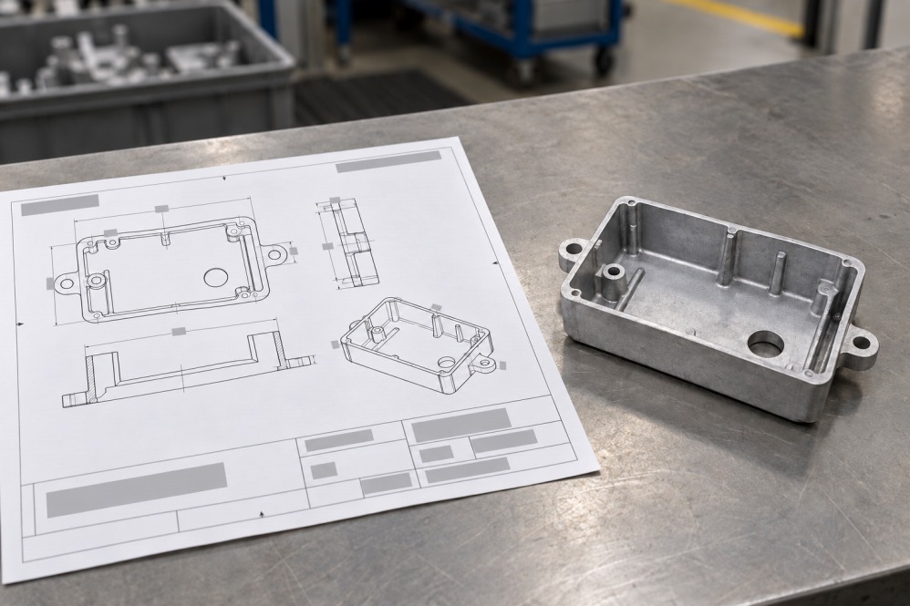
The 3D model shows the intended shape. The 2D drawing defines what variation is acceptable, which features are critical, what must be machined or finished and how the part will be accepted.
The same drawing should not be interpreted by mixing rules from different systems. Common references include ASME Y14.5 and the ISO GPS system, including ISO 1101 for geometrical tolerancing. The drawing should identify the governing standard and edition.
Before quoting, confirm:
If these basics are missing, a precise-looking tolerance box can still produce two different quotations—and two different parts.
| Callout | What it controls | Possible manufacturing impact |
|---|---|---|
| Ø Diameter | Circular feature size | Cast core, drilled/reamed hole, gauge and machining allowance |
| R Radius | Arc or fillet radius | Tool strength, metal flow, stress concentration and machining access |
| ± Size tolerance | Allowed dimensional variation | As-cast capability, CNC requirement and inspection frequency |
| Datum A/B/C | Reference framework for location and orientation | Fixture concept, machining sequence and CMM alignment |
| Flatness | One surface independent of a datum | Cooling balance, warpage control, machining and restraint during measurement |
| Perpendicularity | 90-degree orientation to a datum | Datum setup, secondary machining and functional alignment |
| Parallelism | Orientation parallel to a datum | Machined opposing faces, fixture stability and assembly gap |
| Position | Feature location relative to datums | Hole pattern machining, functional gauge or CMM verification |
| Profile | Variation of a line or surface around the true profile | Casting shape control, datum structure and full-surface measurement strategy |
| Runout | Surface variation during rotation about a datum axis | Machining setup, rotating function and inspection method |
| Ra surface roughness | Surface-texture requirement | As-cast surface, machining, polishing and finishing route |
| Thread callout | Thread system, size, pitch, class and depth | Core-hole strategy, tapping, inserts, gauges and assembly torque |
Symbol appearance and interpretation must follow the standard and edition stated on the drawing. The names above are practical categories, not a substitute for the controlling standard.
A diameter callout does more than describe a round feature. For a die-cast part, the supplier must decide whether the hole can be cast, whether it needs drilling or reaming, and whether its location must be controlled from another feature.
A generous cast hole may reduce machining. A tight bearing bore, sealing diameter or precision thread usually needs secondary machining. The drawing should distinguish the two rather than applying one tight tolerance to every hole.
Radius requirements also affect tooling. Adequate internal radii improve metal flow, reduce stress concentration and avoid fragile sharp features in the die. A tiny internal radius copied from a machined prototype may be unnecessary or impractical in production tooling.
A bilateral tolerance such as ±0.05 mm looks clear, but it does not explain how a feature functions relative to the rest of the part. Applied to every dimension, it can create unnecessary CNC operations and inspection.
Huayinsheng separates dimensions into:
For a detailed explanation of why tighter is not always better, see our article on the hidden cost of over-specifying die-casting tolerances.
Datums establish the reference frame used to orient and locate features. On a die-cast part, a poor datum scheme can create conflict between the drawing, machining fixture, assembly and CMM report.
A useful datum should be:
If datum A is a large, thin as-cast wall that flexes under the inspection fixture, the reported result may depend more on clamping than on the actual manufacturing process.
Flatness controls one surface without needing a datum. It becomes costly when specified tightly across a large, thin casting that naturally responds to ejection, trimming, machining and finishing stresses.
Perpendicularity and parallelism control orientation relative to a datum. These requirements may determine which surface is machined first and how the part is held for later operations.
Before tightening one of these controls, ask what assembly problem it prevents. Sometimes a local mounting pad needs precision; the entire surrounding casting does not.
Position tolerance is commonly used for hole patterns, pins and other features of size. It can communicate functional assembly more effectively than separate ± coordinate dimensions—provided the datum references reflect the actual mating condition.
Profile tolerance can control a complex surface or boundary. On a die casting, that may be useful for a mating envelope or appearance surface. But a profile requirement covering the entire part can also create an expensive full-surface inspection task if the functional need is not clear.
Buyer warning: A GD&T frame is not automatically better because it looks more advanced. It creates value only when it expresses the functional requirement more clearly and can be inspected consistently.
Circular or total runout relates surface variation to rotation about a datum axis. It is relevant for rotating fits, sealing diameters and components where wobble matters.
For many die-cast parts, critical runout features must be machined in a controlled setup. The quotation may need to include a dedicated fixture, datum preparation and indicator or CMM verification.
A surface-roughness requirement should identify the surface and the functional reason. A sealing face, bearing seat or sliding area may need machining and a controlled Ra value. A hidden as-cast wall may not.
Surface texture is also different from visual appearance. A part can meet an Ra requirement and still show color variation, flow marks or coating defects. Decorative acceptance should define A/B/C surfaces, lighting, viewing distance and signed limit samples.
A complete thread callout should communicate system, nominal size, pitch, class and required depth where applicable. The manufacturing team must then choose between:
The decision depends on alloy, engagement length, expected assembly cycles, tightening torque, wall thickness and service load. “M4 thread” alone is not enough for a reliable quotation.
Important requirements are often hidden in general notes rather than attached to one feature. Before quoting, review:
A note that cannot be measured consistently will eventually become a disagreement. Define acceptance method before the purchase order, not after parts arrive.
This is an illustrative manufacturing example, not a disclosed customer case.
Imagine four mounting holes on an ADC12 housing. If their purpose is only to accept clearance screws, a suitable cast pilot and normal drilling operation may be sufficient. If the same holes locate a precision mating assembly relative to a machined sealing face, the drawing may require:
The hole diameter may be identical in both versions. The datum and position requirement—not the amount of aluminum—creates the cost difference.
Huayinsheng commonly works with ADC12 aluminum and Zamak 3/5 zinc alloys on machines from 88T to 400T. To evaluate the part correctly, send:
Our review connects drawing intent to tooling, casting, CNC machining, outsourced surface finishing through qualified long-term partners, inspection, assembly and packaging.
They communicate size, geometry, orientation, location, surface and manufacturing requirements. Their exact interpretation depends on the standard and edition stated on the drawing.
A datum is a theoretically exact reference derived from a feature and used to establish the coordinate framework for locating and orienting other features.
No. Some requirements are achievable as cast, while others need machining. The decision depends on feature location, size, datum structure, parting line, geometry and functional risk.
Yes. Send the 3D model, 2D drawing, quantity and application requirements. We can identify questions affecting tooling, casting, machining, finishing and inspection before the quotation is finalized.
Send Huayinsheng your 3D model and 2D drawing. We will review the features that affect tooling, CNC machining, inspection and total delivered cost.